Buttons & LEDs
The 8-button matrix
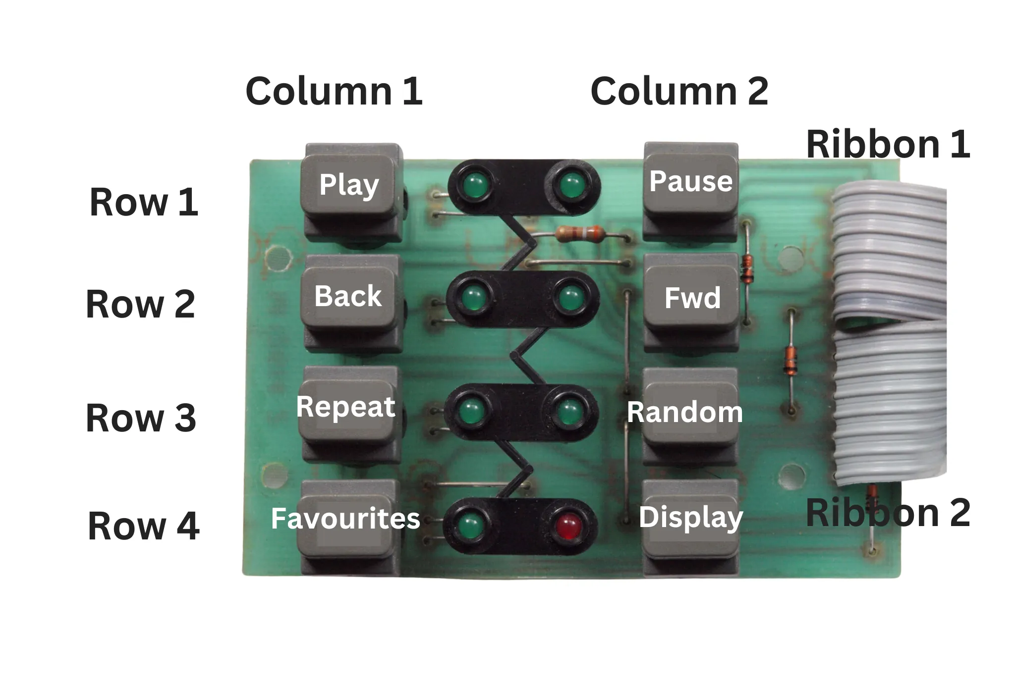
Quadify uses an 8-button matrix configuration. In a matrix, multiple buttons share common rows, while individual buttons are identified by columns.
For example, the Play and Pause buttons share the same row. Pressing a button activates its corresponding column, allowing the system to determine exactly which button was pressed.
When everything is wired correctly, pressing a button should also cause the corresponding LED to light.
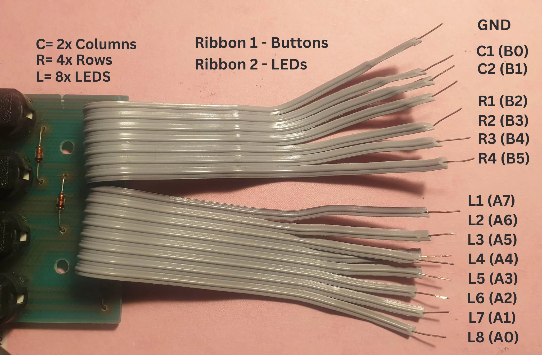
Even though there are eight buttons, the matrix design means you only need six wires.
Remove the button & LED circuit
Carefully desolder and remove the button and LED ribbon cables from the original circuit board.
Once removed, separate and extend the individual wires as needed. Take your time here and use heat-shrink tubing to keep everything tidy and reliable.
Neat wiring at this stage makes troubleshooting much easier later on.
Connecting to the MCP23017
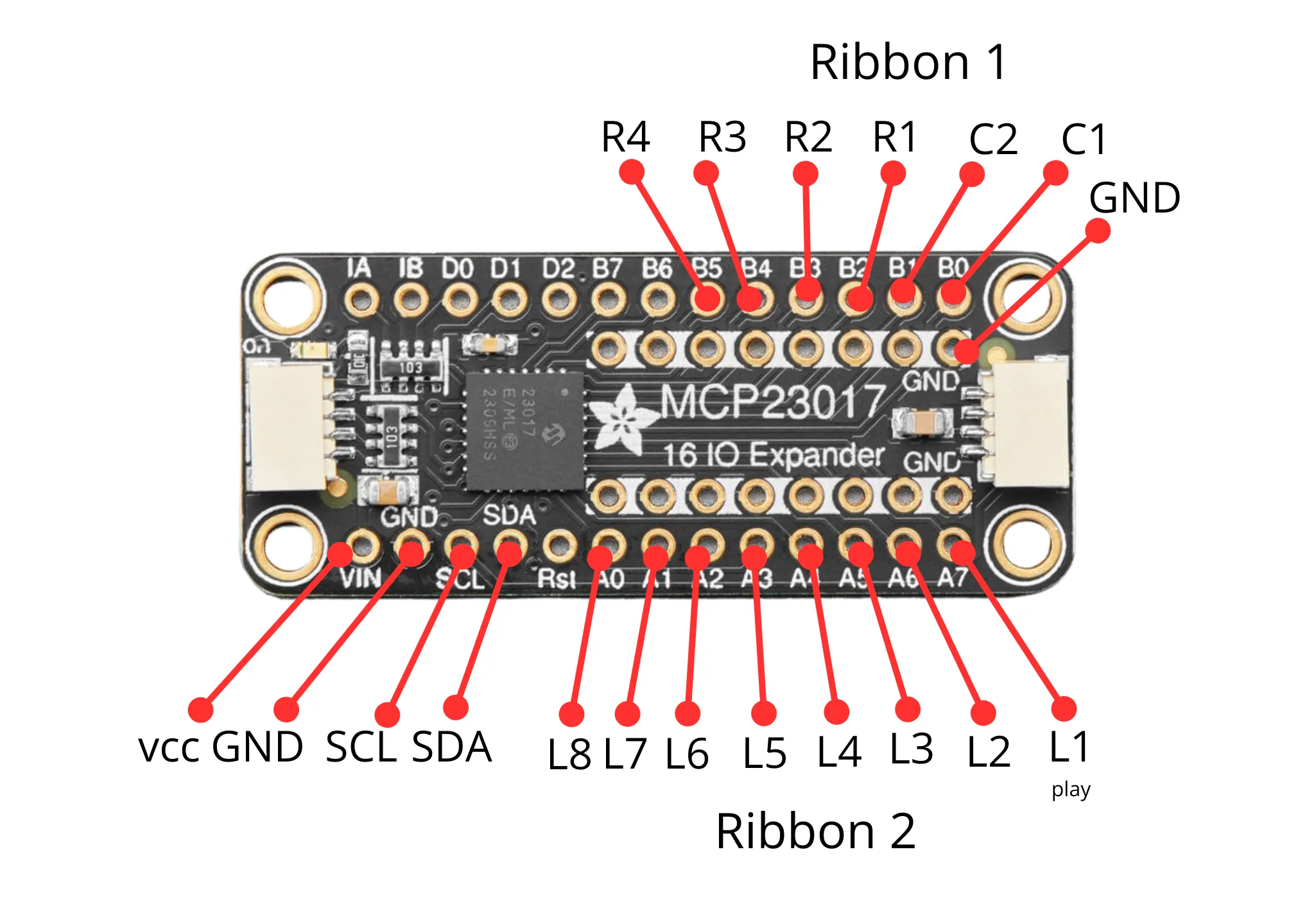
Both the button and LED wiring connect to the MCP23017 GPIO expander:
- LEDs connect to row A (PA0–PA7)
- Button rows and columns connect to row B (PB0–PB5)
This setup allows Quadify to read button presses and control LEDs efficiently while using only a small number of connections to the Raspberry Pi.
Finished board
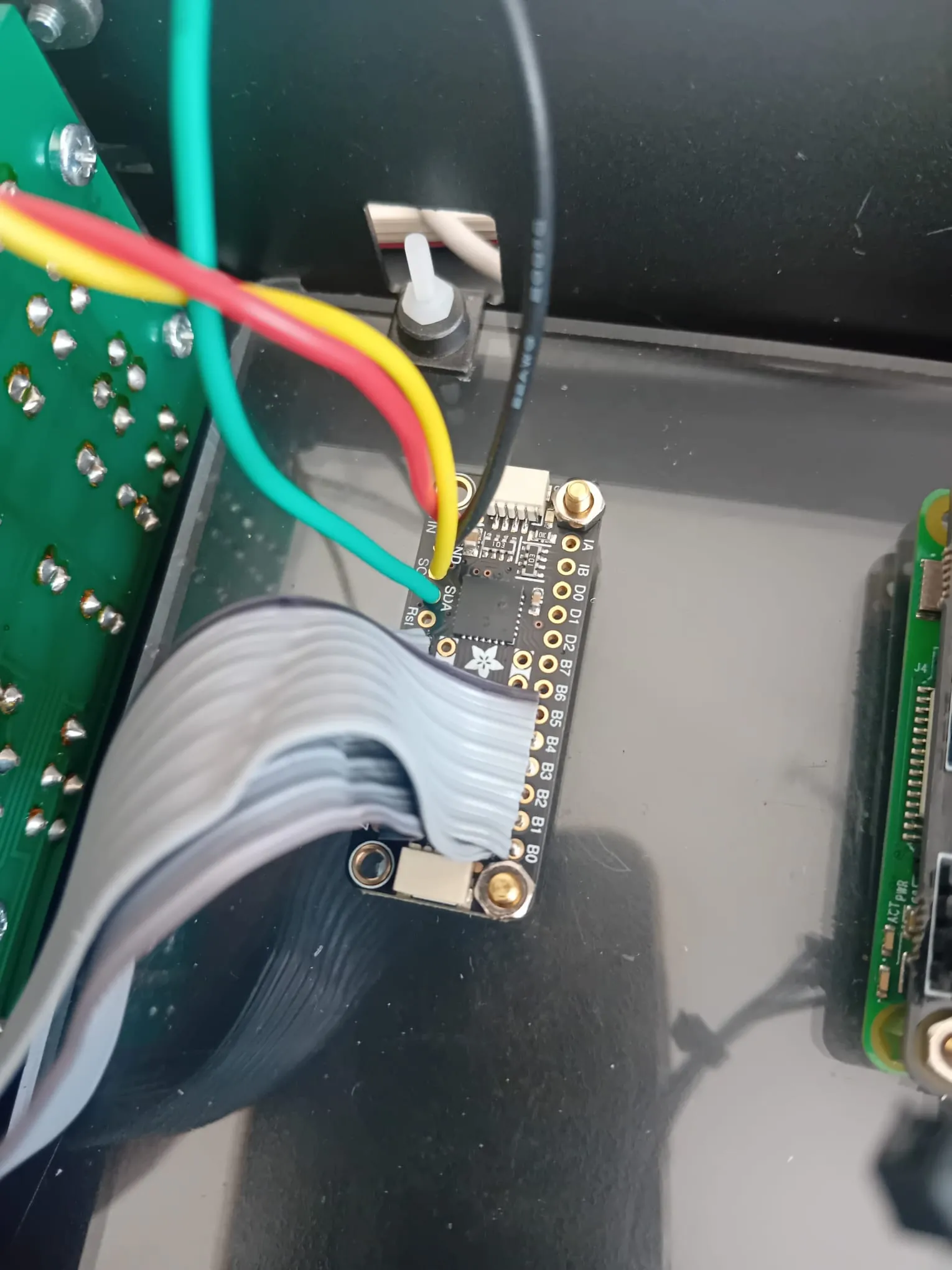
Once complete, the board should look clean, organised, and easy to visually trace.
If a button triggers the wrong LED, it usually means a row or column wire needs swapping, which is normal during first setup.