Wiring the Modules
Wiring overview
Most Quadify modules require power (VCC) and ground (GND), with the exception of the buttons themselves.
To keep things simple during the initial setup, this guide refers to physical pin numbers on the Raspberry Pi header. These pins are also known as GPIOs and can be numbered differently in software, but we won’t go into that here.
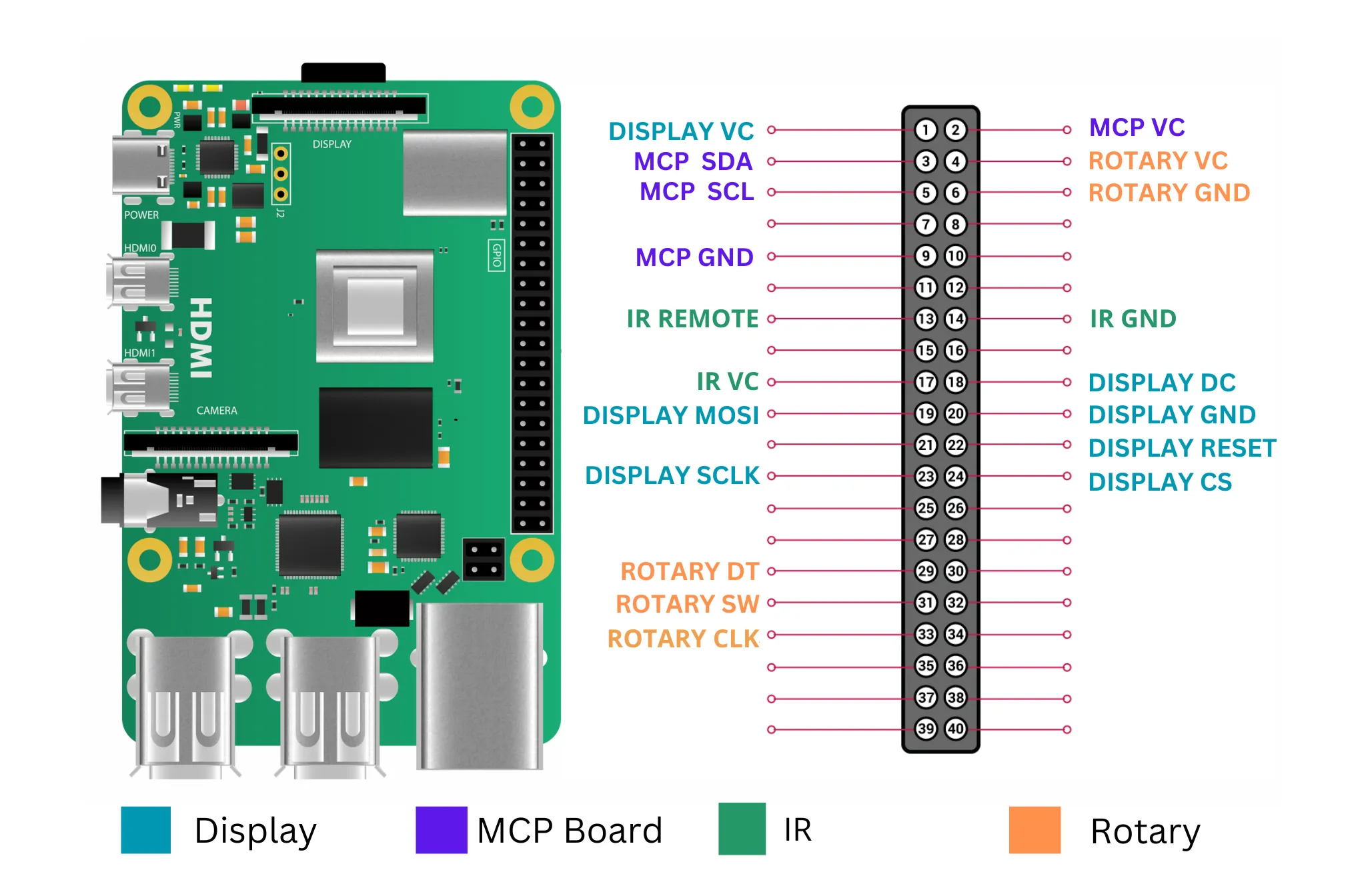
Connecting the OLED screen
- Refer to the wiring diagram above for pin locations
- Connect the screen’s VCC and GND to the Raspberry Pi’s 3.3V and GND pins
- Important: Do not connect the screen to 5V. Although some manufacturers state 5V compatibility, using 3.3V significantly reduces the risk of damaging the display
- Connect the remaining screen pins to the corresponding pin numbers on the Raspberry Pi
- Double-check all connections before applying power
Once everything is working correctly, hot glue can be used to secure the wires more permanently, but only after testing.
Connecting the MCP23017 board
- Refer to the wiring diagram for correct pin placement
- Connect VCC and GND to the Raspberry Pi’s 5V and GND pins
- Connect SDA and SCL to the corresponding Raspberry Pi GPIO pins
- Ensure PA0–PA7 are connected to the LED lines on your button/LED PCB
- Ensure the buttons are connected to PB0–PB5
Connecting the rotary switch
- Connect VCC and GND first
- Connect DT, CLK, and SW to individual Raspberry Pi pins
- Ensure the pins are connected in the correct order
The Sable software will not start if the rotary switch is not connected correctly.
Using a Terminal HAT (recommended)
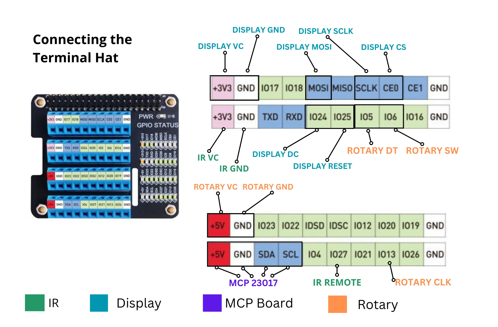
This is the recommended method, particularly if you are not confident with soldering or plan to transport or ship units.
- Power down the Raspberry Pi and disconnect all power
- Carefully attach the IQaudio DAC to the Raspberry Pi GPIO header
- Connect the ribbon cable to the DAC’s GPIO extension pins
- Connect the other end of the ribbon cable to the Terminal HAT
- Secure all components using screws or clips where provided
- Ensure the ribbon cable is not twisted or under strain
Once complete, power can be restored. No software changes are required when using a Terminal HAT.
Screen problems
Once connected, the screen should work out of the box. If you experience issues, double-check wiring and power first.
A small number of screens were shipped with incorrect resistor placement. If you suspect this is the case, please get in touch via Discord for further guidance.