Get Started
Get some tunes playing
Before worrying about screens, buttons, or fitting everything into an FM4 case, the first goal is simple: get music playing reliably through your existing hi-fi.
1. Raspberry Pi 4 (4GB)
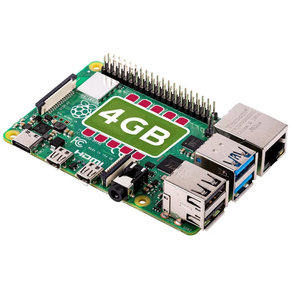
The Raspberry Pi 4 (4GB Model B) is the core of the Quadify system and provides more than enough performance to run Volumio smoothly without pushing system limits.
When buying a Raspberry Pi, stick to official UK resellers to ensure you receive a genuine board at a fair price, with proper packaging and support.
Avoid third-party sellers on Amazon where prices are often inflated by bulk resellers.
2. Storage: microSD or USB
To set up your Raspberry Pi for the FM4 Quadify project, you’ll need reliable storage to install the Volumio operating system. The Raspberry Pi 4 supports both microSD cards and USB storage, so you can choose whichever suits your setup best.
Boot options: microSD card vs USB storage
Traditionally, Volumio is installed on a microSD card. However, the Raspberry Pi 4 can also boot directly from a USB flash drive or SSD, which can offer slightly faster boot times and easier access to the storage for updates or tweaks.
Option 1: Using a microSD card
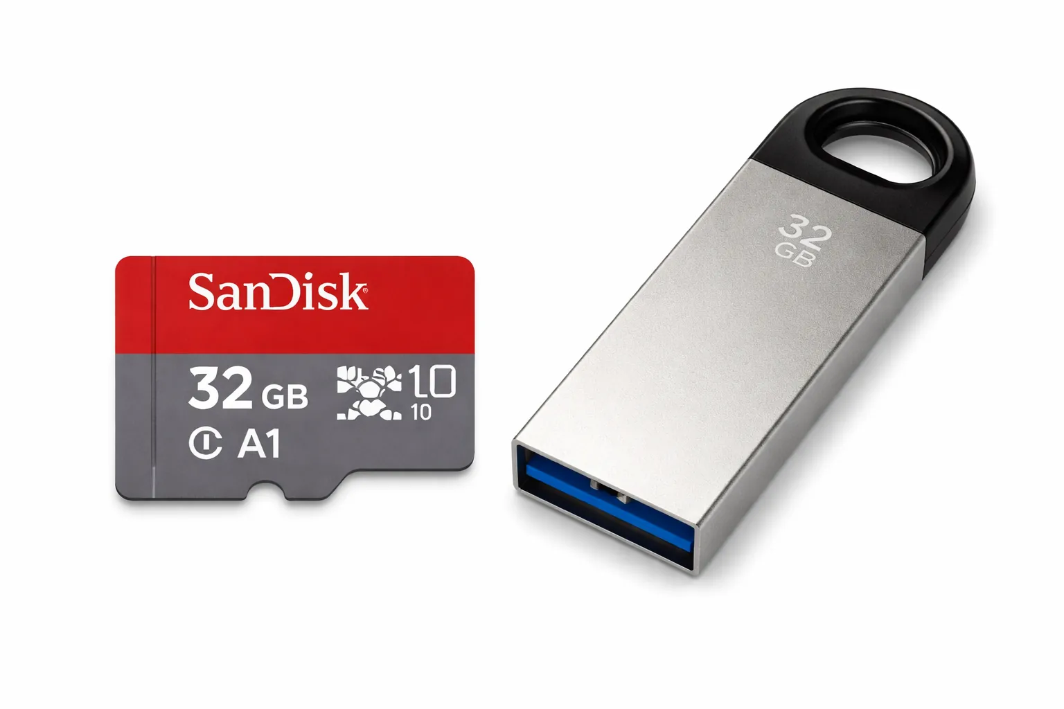
Investing in a good-quality microSD card is important for performance and long-term reliability. Cheaper cards may work initially but can suffer from slow speeds or early failure.
Recommended specifications:
- Capacity: 32GB or higher
- Speed Class: Class 10, UHS-I (U1 or U3)
- Application Performance Class: A1 or A2
Recommended card:
SanDisk 32GB microSD (tested and reliable for Raspberry Pi setups)
View on Amazon
microSD card reader:
If your computer doesn’t have an SD card slot, you’ll need a USB card reader
to write the Volumio image.
Recommended: The Pi Hut Mini USB 2.0 microSD Card Reader
View at The Pi Hut
Option 2: Booting from USB storage
Volumio can also boot directly from USB flash drives or SSDs connected to the Raspberry Pi. This is a good alternative if you don’t have a microSD card reader or want slightly quicker boot times.
- Slightly faster boot performance
- Easier access to storage for updates or troubleshooting
- No microSD card or reader required
Recommended USB drive:
SanDisk 32GB Ultra Fit USB 3.2 Flash Drive
View on Amazon
The setup process is identical for both options. Use Raspberry Pi Imager to write Volumio to your chosen storage, then plug it into the Pi and boot. Raspberry Pi 4 supports USB booting by default.
3. USB-C Power Supply

To power your Quadify setup, there are a few options depending on how far you plan to take the build. For most people, the simplest and safest choice is a high-quality USB-C power supply.
The official Raspberry Pi USB-C power supply is strongly recommended. It is designed to deliver clean, stable current and has more than enough capacity to run the Raspberry Pi, DAC, OLED screen, rotary encoder, and IR receiver without issues.
Recommended power supply:
Official Raspberry Pi USB-C Power Supply (5.1V / 3.0A)
Available from The Pi Hut and other official retailers.
Power cable tips
- If you’re routing power through a case such as the FM4, consider using a slightly longer USB-C cable so it can reach a nearby wall outlet neatly.
- The cable can be passed through rear panels or side vents to keep external wiring tidy and unobtrusive.
Note on 240V power integration
In some custom builds, a 240V inline mains switch is used inside the case to power both the Quadify internals and additional equipment. This is optional and not required for a standard build.
⚠ Working with mains electricity is dangerous. If you are not confident or experienced with 240V wiring, do not attempt internal mains modifications. Always prioritise safety and consult a qualified electrician if you’re unsure.
4. DAC HAT: HifiBerry DAC+
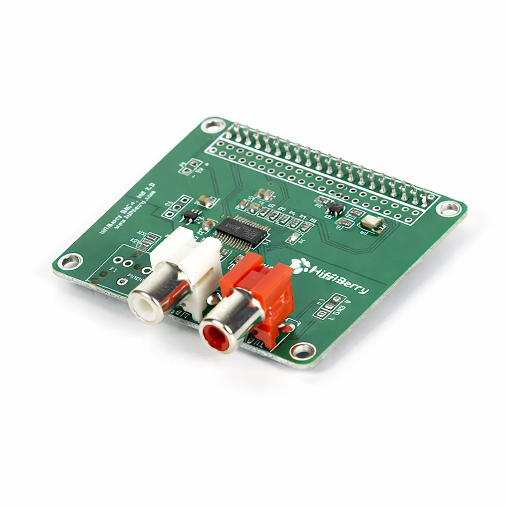
When building your Quadify DAC, choosing the right DAC HAT (Digital-to-Analog Converter) is important for both sound quality and compatibility. While there are many Raspberry Pi DACs available, not all are truly plug-and-play; some use GPIO pins in ways that complicate the build or require custom configuration.
For the smoothest experience, the HifiBerry DAC+ is strongly recommended. It offers excellent audio performance and works seamlessly with both Quadify and Volumio, with no additional setup required.
Where to buy:
Both versions are functionally identical, so choose whichever retailer suits you best.
Why HifiBerry?
- Proven compatibility: Fully tested with Quadify and Volumio for a reliable, plug-and-play experience.
- GPIO pass-through: Leaves GPIO pins available for buttons, rotary encoders, LEDs, and OLED displays.
- No modifications required: No custom pin remapping or special drivers needed.
⚠ Important Note on DAC Compatibility
When selecting a DAC HAT, it’s essential to consider how it uses the Raspberry Pi’s GPIO pins. Some DACs occupy pins required for OLED displays, buttons, or LEDs, which can lead to conflicts or components not working correctly.
- GPIO pin conflicts: Certain DACs reserve GPIO pins that Quadify relies on for user controls and displays.
- Limited GPIO availability: The Raspberry Pi has a finite number of pins, and heavily occupied layouts can limit expansion.
The HifiBerry DAC+ is known to coexist cleanly with other Quadify hardware, avoiding these issues and keeping the build straightforward.
Using other DACs
If you choose a different DAC, make sure to:
- Confirm it is supported by Volumio
- Check which GPIO pins it uses or blocks
- Be prepared to adjust Quadify wiring and configuration if needed
Some high-end DACs sound excellent but may limit GPIO access or require extra setup, making them less suitable for Quadify builds that rely on physical controls.
5. RCA Cables
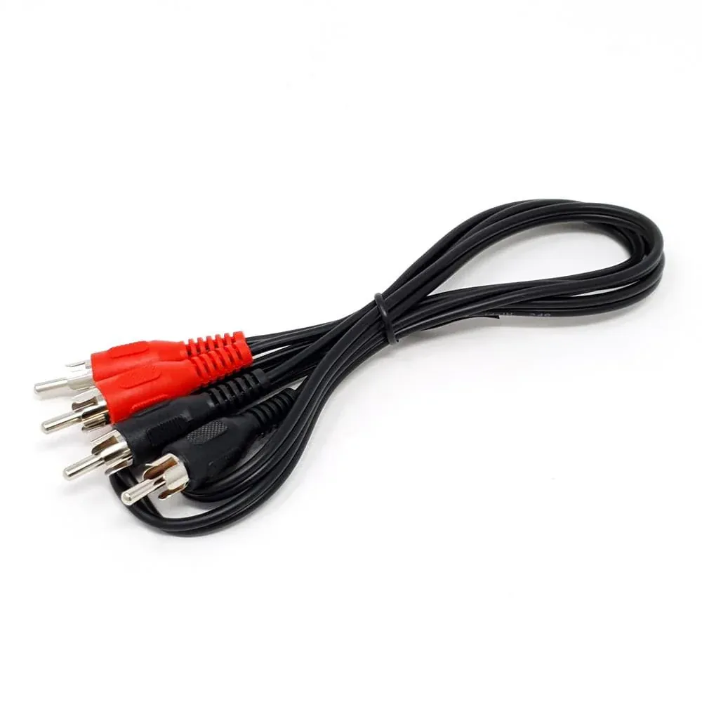
You probably already own some, but ordering a spare pair avoids frustration later during testing.
Display & Controls
With music playback confirmed, Phase 2 is where Quadify becomes interactive. This stage adds the screen, rotary control, and expanded GPIO needed for a proper front-panel interface.
- OLED display for track, volume, and system status
- Rotary encoder for tactile navigation and control
- GPIO expansion to support buttons and LEDs
Take your time here: careful pin planning and tidy wiring will save hours later.
6. MCP23017 I/O Expansion Board
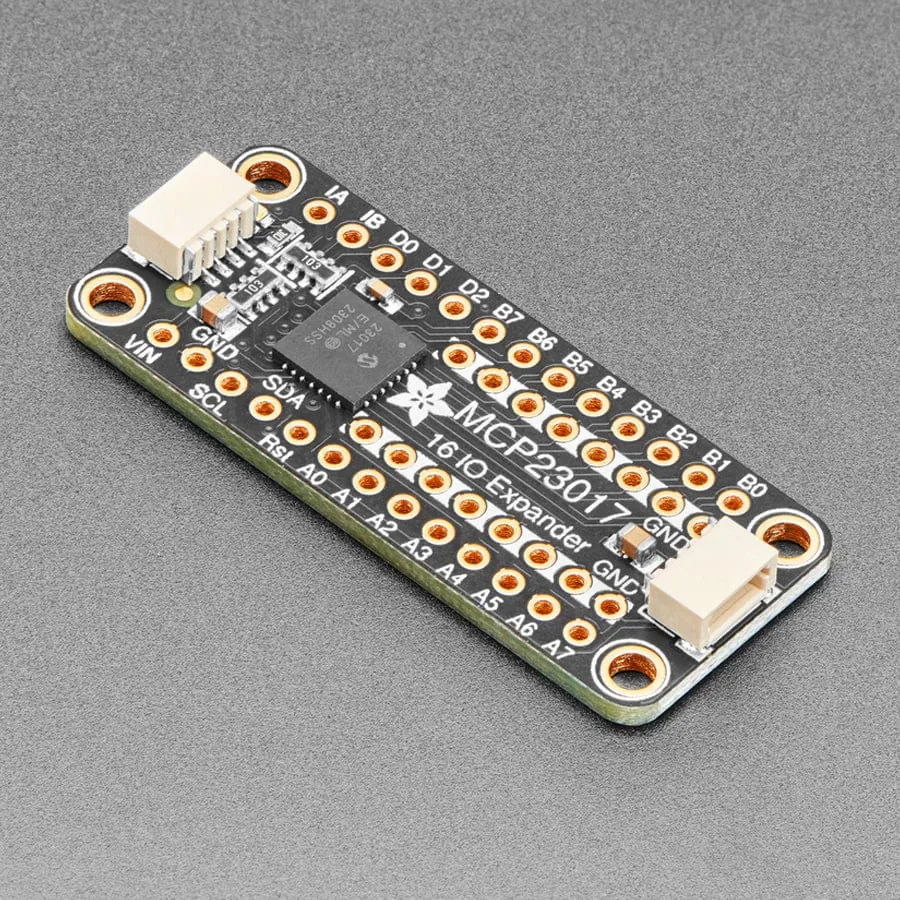
In the FM4 Quadify project, you may find that the Raspberry Pi doesn’t have enough native GPIO (General Purpose Input/Output) pins to connect all the buttons, LEDs, and controls you’d like to use. The MCP23017 I/O Expansion Board solves this neatly by adding extra GPIO without complicating the setup.
What it does
- Expands GPIO pins: Adds 16 additional GPIO pins, giving you far more flexibility for buttons, LEDs, and other inputs.
- Simple connection: Communicates over I²C using just two data lines (SDA and SCL).
How it works
The MCP23017 connects to the Raspberry Pi using four jumper wires: SDA, SCL, power (3.3V or 5V depending on the board), and GND. Once connected, your buttons and LEDs are wired to the MCP23017 instead of directly to the Pi.
A common approach is to dedicate one bank of pins to LEDs and another to buttons, but the exact layout is flexible and will be covered later in the wiring guides.
Where to buy:
The Pi Hut: MCP23017 I/O Expansion Board
By using the MCP23017, you avoid exhausting the Raspberry Pi’s built-in GPIO pins while keeping the wiring clean and scalable.
7. SSD1322 OLED Display (SPI)
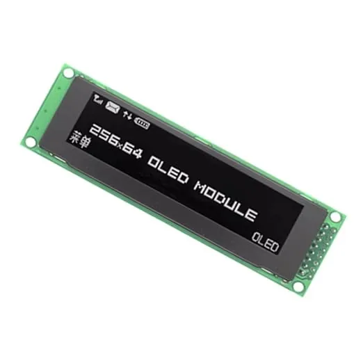
For the FM4 Quadify project, you’ll need a 2.8-inch OLED display with a 256×64 resolution, powered by the SSD1322 driver and using an SPI interface. This screen is used to display track information, volume levels, and other Quadify UI elements.
Key specifications
- Size: 2.8 inches
- Resolution: 256×64 pixels
- Driver: SSD1322
- Interface: SPI (not I²C or parallel)
- Colour: White (preferred for clarity and contrast)
Where to buy
Prices vary widely depending on the supplier:
- Amazon: ~£50
- eBay: ~£30
- AliExpress: ~£10–£15
Recommendation: AliExpress usually offers the best value. Make sure the listing explicitly states SSD1322 and SPI, as visually similar displays may use different drivers or interfaces.
Important notes
- Compatibility: The display must be SPI-based and use the SSD1322 driver.
- Physical size: Some variants are a few millimetres larger and may not fit the 3D-printed holders available through me.
- Best variant: The green PCBs with a 16-pin header are the most reliable and easiest to work with.
If you’re unsure about a specific listing, feel free to check before ordering, since it’s easy to buy the wrong variant by mistake.
8. Rotary Encoder (KY-040)
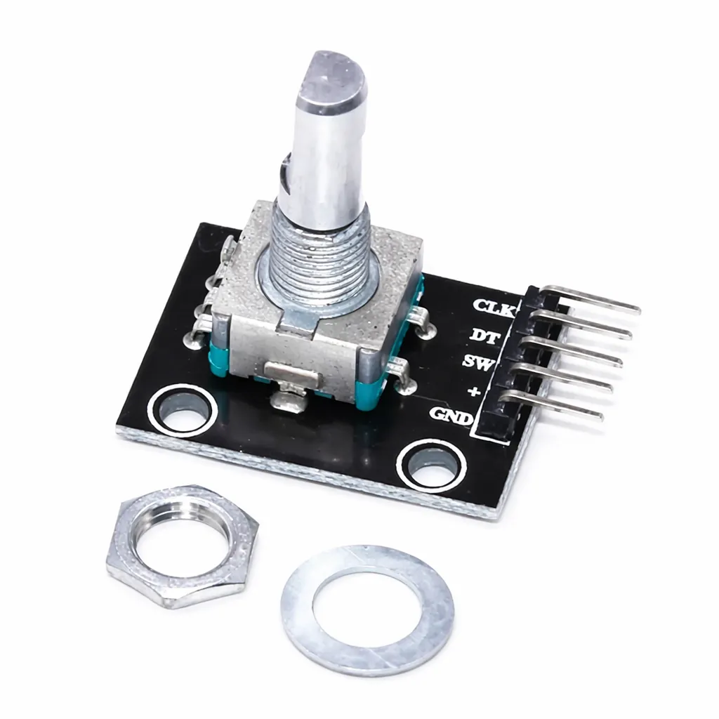
The KY-040 rotary encoder is used in the FM4 Quadify project to control volume and navigate menus within the Quadify interface. It provides a tactile, infinitely rotating control with a built-in push-button, making it both intuitive and satisfying to use.
What to look for
- Module name: KY-040
- Pins: 5-pin interface (CLK, DT, SW, +, GND)
- Mounting: PCB-mounted encoder module (on-board resistors are common and helpful)
Where to buy
- Amazon: Occasionally available; search for “KY-040 Rotary Encoder Module”
- eBay: KY-040 Rotary Encoder Module (UK sellers common)
- AliExpress: Lowest prices (~£1–£3); search for “KY-040 rotary encoder”
💡 Some listings include jumper wires, which can be handy if you don’t already have spares.
Why the KY-040?
- Works seamlessly with the Raspberry Pi and MCP23017 via GPIO
- Push-to-click functionality for menu selection
- Widely supported in Python with existing libraries and examples
This encoder gives Quadify a proper physical interface and is a key part of making the system feel responsive and hands-on.
9. Jumper Wires (Female-to-Female)
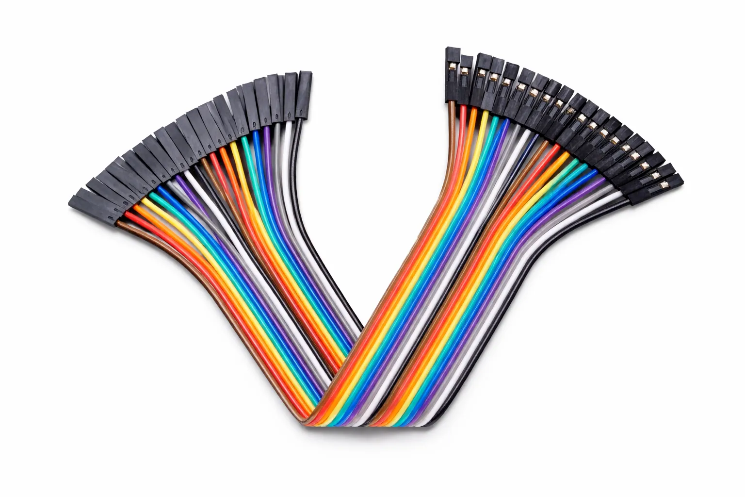
You’ll need a set of female-to-female jumper wires to connect the OLED display, rotary encoder, and MCP23017 I/O expander to the Raspberry Pi or expansion headers. These are essential for flexible, tool-free wiring during your FM4 Quadify build.
What to look for
- Connector type: Female-to-female
- Length: ~20cm (a good balance for internal routing)
- Quantity: 40 wires per set is typical
- Pitch: 2.54mm (standard GPIO spacing)
- Colour: Multicoloured helps with tracing connections
Where to buy (UK)
- eBay: 40pcs Female-to-Female Jumper Wires (20cm), approx. £3–£4
- The Pi Hut: Occasionally in stock; search for “jumper wires” (£4–£5)
- Pimoroni: Usually part of mixed jumper kits, approx. £5–£6
💡 Make sure the set is female-to-female, not male-to-male or mixed, unless you’re buying for multiple projects.
Advanced setups (optional)
These steps involve mains voltage. Proceed only if you know what you’re doing.
10. Internal 5V Power Supply
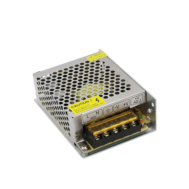
Allows the Raspberry Pi and accessories to be powered internally while retaining the original FM4 mains passthrough.
11. Original FM4 Power Switch
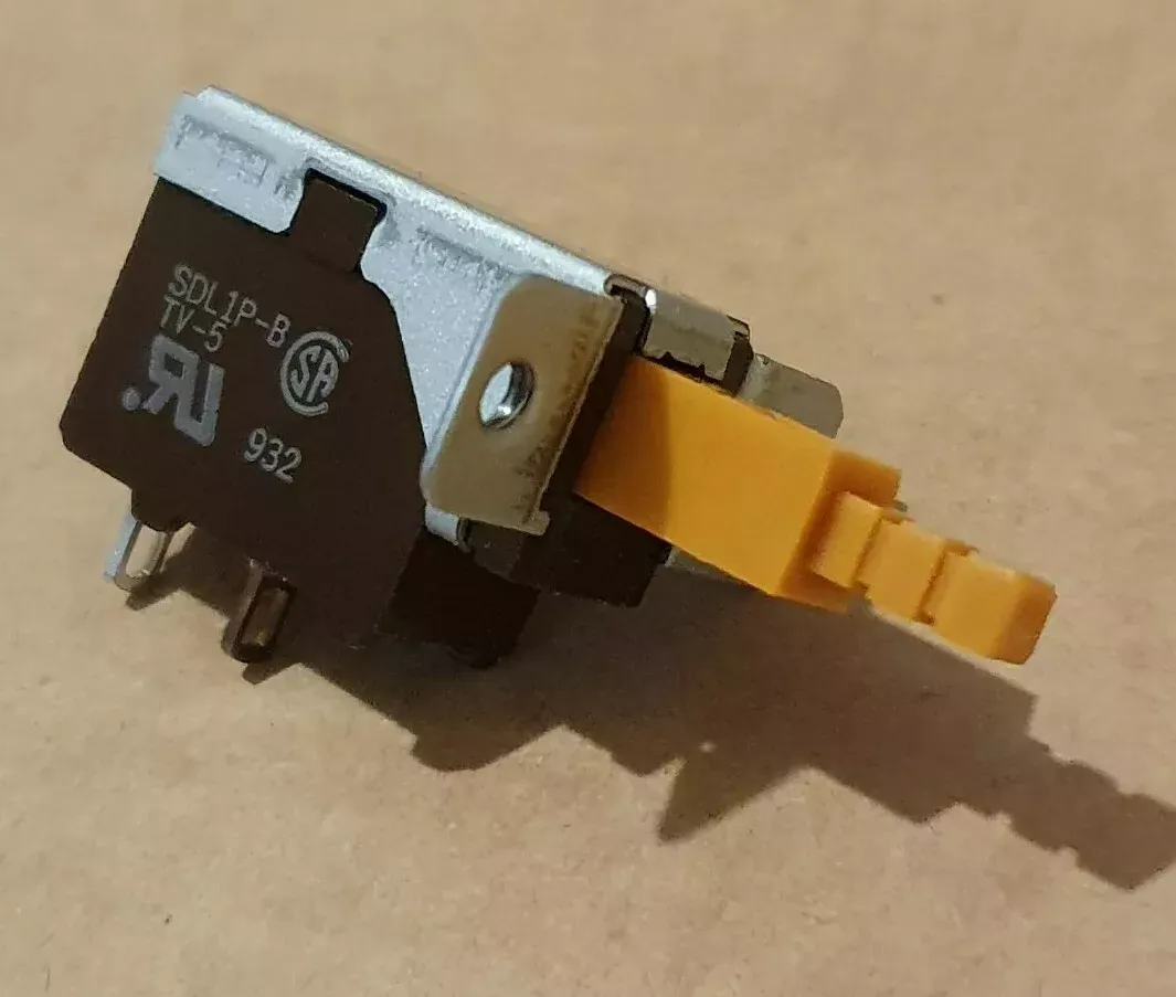
Reusing the original switch preserves the FM4 look and controls both the internal PSU and mains passthrough.
12. Base & 3D-Printed Screen Holder
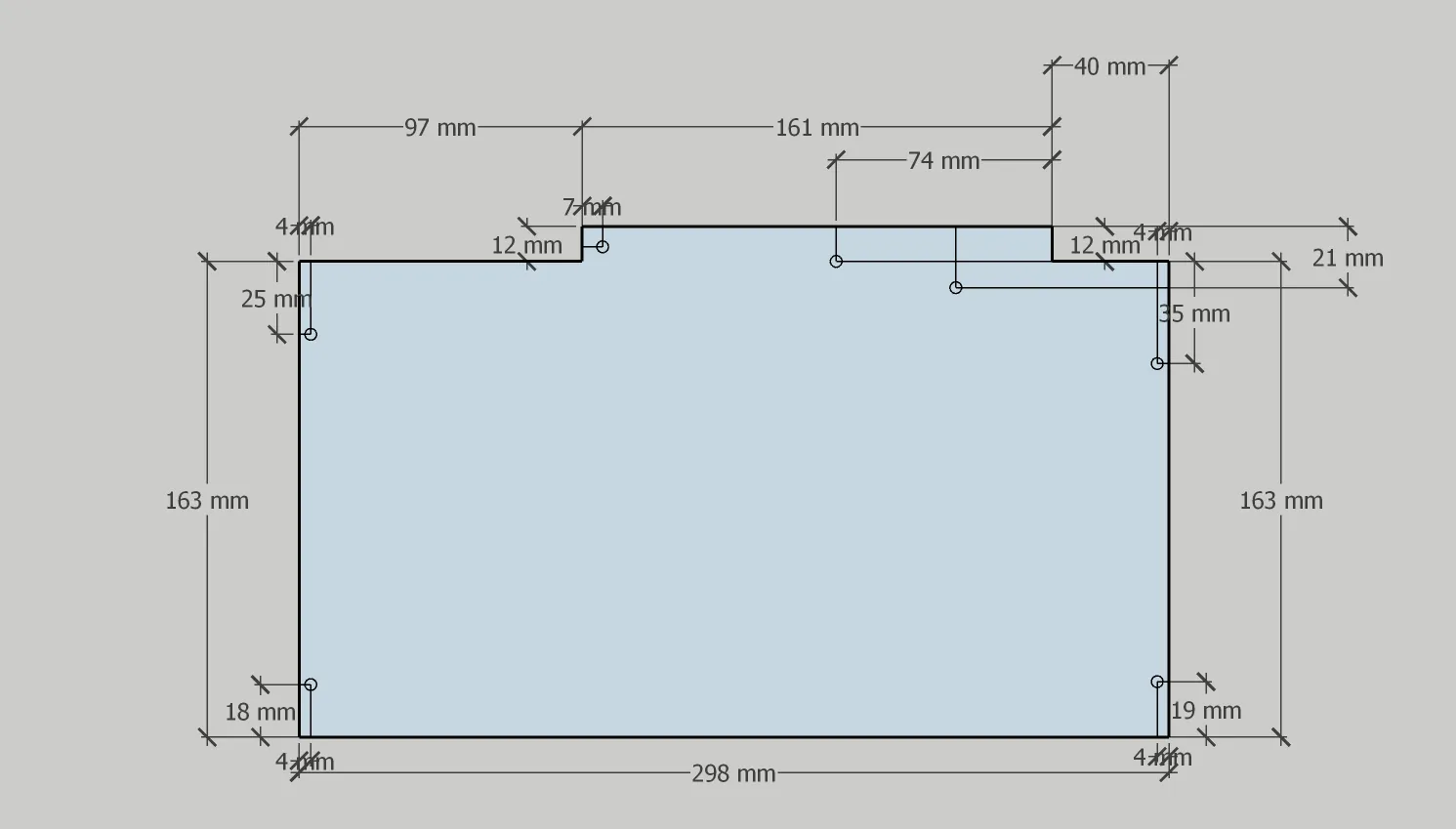
A clear perspex base and custom 3D-printed holder provide secure mounting for the new electronics and OLED display.